
Rigid-Flex PCB Manufacturing: Materials, Design Capabilities & Industrial Applications
May 15, 2025


In today’s electronics industry, the demand for smaller, lighter, and more reliable devices is growing across all sectors. Rigid-flex PCB technology stands at the forefront of this evolution, offering a sophisticated interconnection solution that combines the stability of rigid boards with the versatility of flexible circuits. These hybrid PCBs address critical design challenges in applications where space constraints, harsh operating environments, and reliability requirements pose significant hurdles for traditional circuit board designs.
This article will cover everything you need to know about rigid-flex technology, its advantages, and its role in resolving design challenges.
Rigid-Flex printed circuit boards are a type of PCB made using a combination of flexible and rigid board technologies integrated within a single interconnected structure. Unlike traditional rigid boards or purely flexible circuits, rigid-flex PCBs feature a seamless transition between rigid and flexible zones, creating a three-dimensional electronic packaging solution that eliminates the need for connectors between board sections.
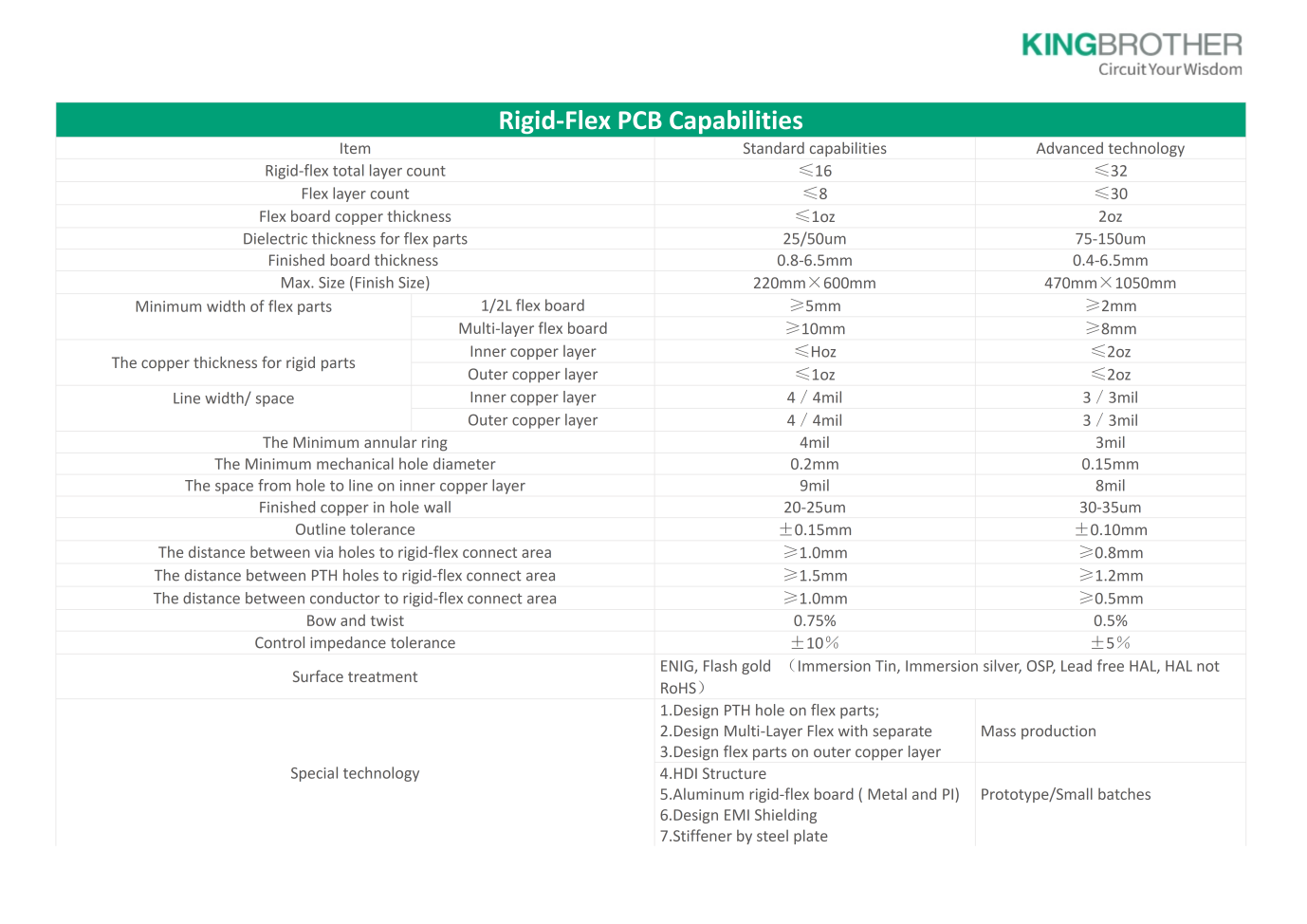
The performance and reliability of rigid-flex PCBs depend heavily on material selection, which must be carefully tailored to the application’s specific requirements. Key materials include:

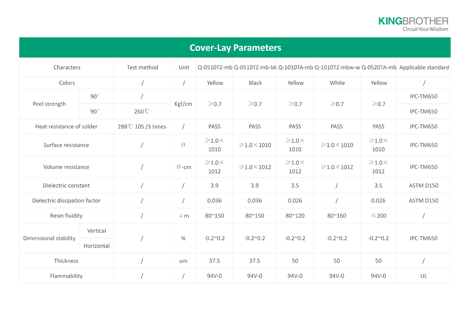
Cover-lay is a thin, flexible dielectric film that is laminated onto flex circuits to protect the traces on the board. As the main component is Polyimide (PI), it is also referred to as a PI covering film.
Common specifications:

Material selection criteria must account for operating temperature range, number of flex cycles, bend radius requirements, and environmental factors such as humidity and chemical exposure. PCB design engineers must carefully balance these factors when specifying materials for rigid-flex applications.
Understanding the fundamental differences between rigid, flex, and rigid-flex PCB technologies is essential for selecting the most appropriate solution for specific applications:
| Characteristic | Rigid PCB | Flex PCB | Rigid-Flex PCB |
| Structure | Solid laminate material | Thin flexible substrate | Combination of rigid and flexible layers |
| Dimensional stability | Excellent | Limited | Excellent in rigid areas |
| Flexibility | None | Throughout the entire board | Only in designated areas |
| Component mounting | Both sides possible | Limited to one side, typically | Both sides of the rigid sections |
| Z-axis packaging | Limited to planar design | 3D packaging possible | Optimized 3D packaging |
| Connector requirements | Many | Reduced | Minimal or eliminated |
| Reliability in dynamic applications | Lower | Good | Excellent |
| Manufacturing complexity | Low | Medium | High |
A rigid-flex PCB assembly offers numerous technical advantages that make it ideal for solving complex design challenges:
Space and Weight Reduction: Rigid-flex PCBs eliminate the need for board-to-board connectors. This is particularly valuable in aerospace, medical, and portable consumer electronics applications.
Enhanced Reliability: By eliminating connectors and solder joints, rigid-flex PCBs remove the most common failure points in electronic assemblies. The reduction in interconnection points also improves signal integrity by reducing impedance discontinuities.
Improved Signal Integrity: Controlled impedance design can be maintained across both rigid and flexible sections, enabling high-speed data transmission with minimal signal degradation. This is increasingly important for applications running at frequencies above 1 GHz or utilizing high-speed serial protocols.
3D Packaging Capabilities: Rigid-flex PCBs enable innovative three-dimensional packaging solutions that would be impossible with traditional rigid boards. This allows for optimization of the entire electronic assembly to match the shape of the final product, rather than forcing the product design to accommodate rectangular circuit boards.
Assembly Process Improvements: With fewer separate boards and connectors, assembly complexity is reduced. This translates to higher manufacturing yields and more reliable products, particularly important for high-value or safety-critical applications.
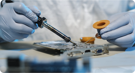
Despite their advantages, rigid-flex PCBs present several manufacturing challenges that must be carefully managed:
KINGBROTHER addresses these challenges through a combination of advanced manufacturing processes, specialized equipment, and extensive experience in rigid-flex PCB fabrication.
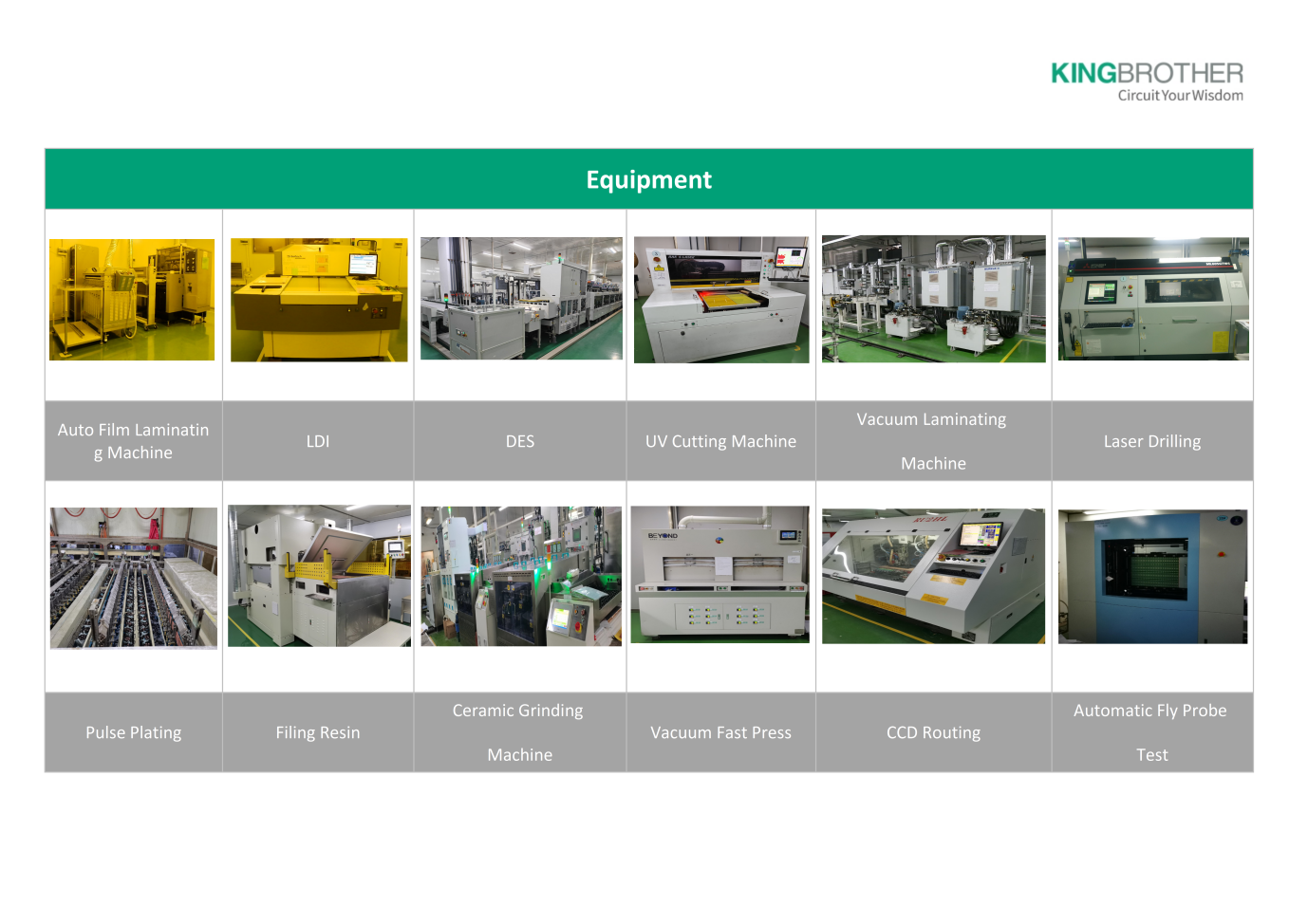
By proactively addressing these manufacturing challenges, KINGBROTHER ensures the reliable production of even the most complex rigid-flex PCB designs.
Now that you have familiarized yourself with the basics of rigid-flex PCB assembly, here are the recommended guidelines for designing and manufacturing this technology.
Creating effective rigid-flex PCB designs requires careful consideration of the unique characteristics of these hybrid structures:
KINGBROTHER’s design support team works closely with clients to develop optimal stack-up designs that balance performance requirements with manufacturing constraints, ensuring reliable and cost-effective rigid-flex PCB solutions.
Effective routing of rigid-flex PCBs requires specialized techniques to ensure reliability and performance:
By following these PCB design guidelines, engineers can maximize the benefits of rigid-flex technology while avoiding common pitfalls that can lead to manufacturing or reliability issues.
Ensuring the reliability of rigid-flex PCBs requires specialized testing approaches that address their unique construction:
KINGBROTHER’s quality assurance system incorporates these specialized testing protocols along with standard IPC compliance verification. Our facilities maintain ISO 9001, ISO 13485, and industry-specific certifications, ensuring that every rigid-flex PCB meets both international standards and customer-specific requirements.
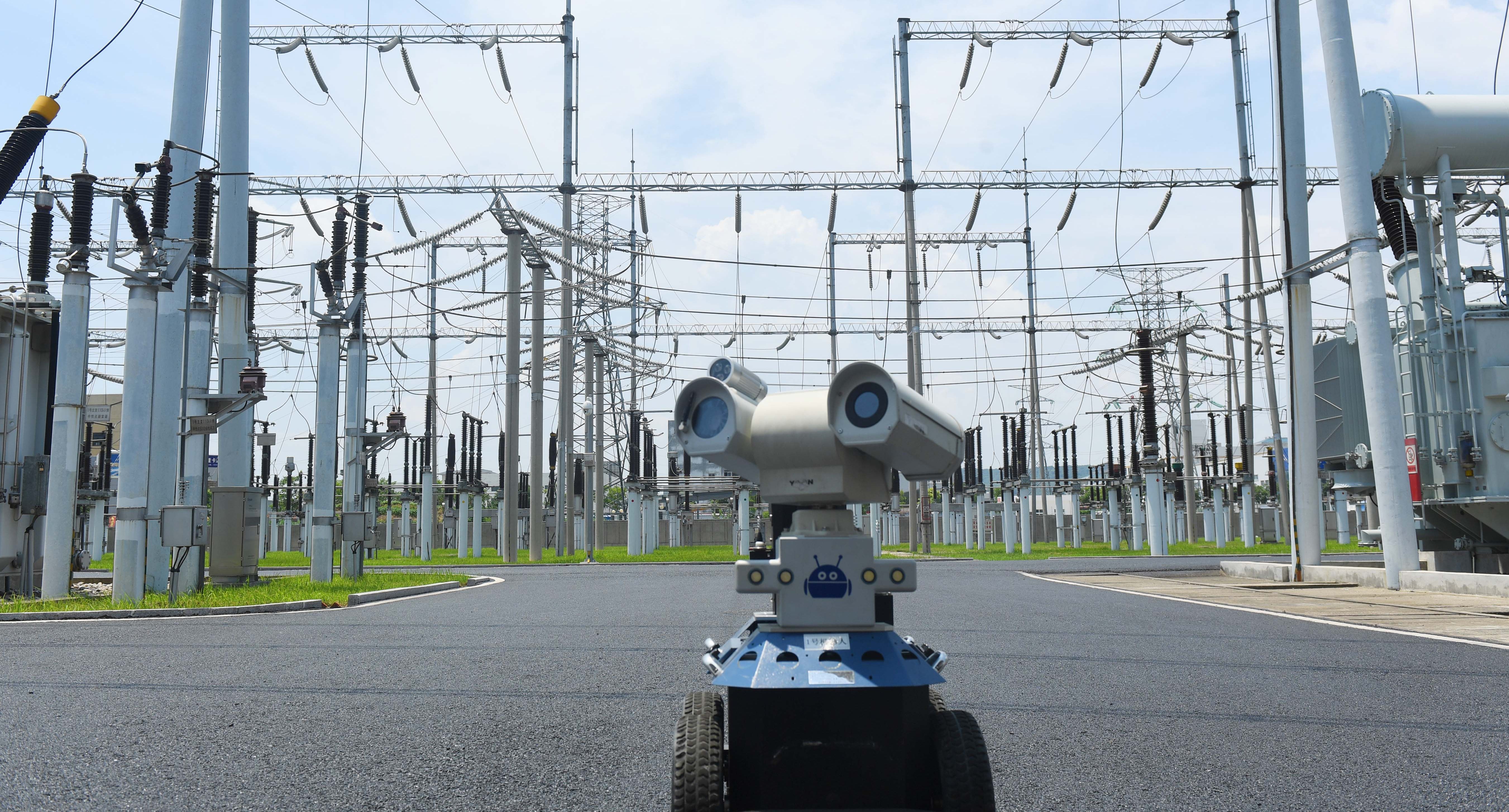
There is a wide range of applications for rigid-flex printed circuit boards, from smart devices to cell phones and digital cameras. For their space and weight reduction capabilities, rigid-flex board fabrication has been used in medical devices, such as pacemakers. Relying on the same merits, rigid flex PCB usage can be applied to smart control systems.
Furthermore, rigid-flex PCBs can be utilized to benefit nearly all advanced electrical applications, including testing equipment, tools, and automobiles.
What makes rigid-flex circuits stand out is their reliability, compact size, and low weight. In addition, you can build them to precisely fit the device they fit into. Manufacturers are under pressure to fit higher-end technology into smaller spaces, so rigid-flex circuits are a great choice. They allow for a denser device population with lighter conductors while maintaining a high level of flexibility.
There are several other benefits of rigid-flex circuits. These include lower costs for rigid-flex PCB manufacturers and improved connection reliability, polarity, and flexibility in packaging. Moreover, rigid-flex circuits are highly reliable and can be easily integrated into various applications. They are less expensive than traditional circuit boards and can be beneficial in high-density applications.
Furthermore, you can manufacture these rigid-flex circuits in various sizes and densities. For example, polyimide circuit boards can have a high density of connection points, enabling high-density circuit routing. Rigid-flex circuits also minimize the overall weight of a system. As a result, they are ideal for high-shock and vibration applications.
KingBrother’s Rigid Flex PCB applications include:
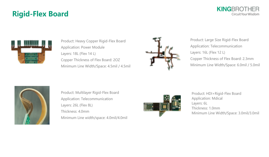
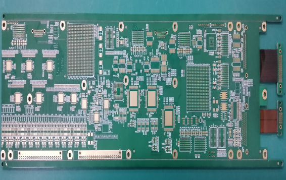
High Speed Multi-Layer Rigid-Flex (20L)

Unsymmetry Flex Design(16L)
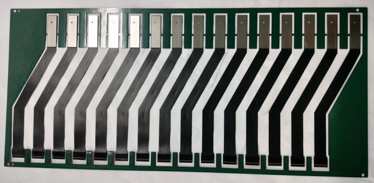
Stiffener by Steel Plate
The rigid-flex PCB industry continues to evolve, with several emerging trends that promise to expand capabilities and applications:
KINGBROTHER remains at the forefront of these developments, with ongoing research and development initiatives focused on expanding the capabilities of rigid-flex PCB technology and making it more accessible to a wider range of applications.
Rigid-flex PCB technology offers a powerful solution for electronic design challenges by seamlessly combining rigid boards with flexible circuits, enabling innovative 3D packaging with enhanced reliability in a single interconnected assembly. When evaluating this technology for your application, consider key factors including space constraints, reliability requirements in harsh environments, signal integrity needs, assembly simplification, and lifecycle considerations. Despite higher initial costs, rigid-flex PCBs typically deliver compelling value through comprehensive benefits — reduced size and weight, enhanced durability, simplified assembly, and improved signal integrity, making them the optimal choice for demanding applications where conventional approaches fall short.
As a leading rigid-flex PCB manufacturer, KINGBROTHER specializes in delivering high-performance solutions that meet the exacting needs of industries ranging from medical devices to telecommunications infrastructure. Our expertise in fast-turn rigid-flex PCB production enables rapid prototyping and development cycles, helping engineers bring innovative products to market more efficiently.
Contact us today to discuss your rigid-flex PCB requirements and discover how our expertise can help bring your innovative designs to life with optimal performance, reliability, and cost-effectiveness.

